Two-Wheeled Vision Robot
This project is currently in progress, so this write-up is not finished.
Background
As the current Software Co-Lead of ARVP, I decided that I wanted to learn more about the other systems that make the robot work. What better way to do this than make my own robot? I decided to make a robot that uses two wheels for a few reasons:
- It is cheaper than other form factors while allowing for equivalent movement.
- There are a few examples of this on the internet, so I knew it was possible (Though my implementation is different from most of them).
- It allows me to learn about more advanced control systems.
Shopping for Hardware
After this was decided, I needed to figure out the materials I needed. What was clear is that I needed a microcontroller, some motors, and an inertial measurement unit (IMU) to allow the robot to balance itself.
I decided on the MPU6050 IMU because it is widely used and cost-effective. I went with an ESP-32 for the microcontroller because it was cheap, and had dual cores. This would allow me to run the PID balance controller on one core and the others tasks on the other core, via the FreeRTOS-based software on the ESP-32. The motors were the hardest part to figure out, since I don’t really know much about motors as a CS student. Since it seemed like most batteries I could use at this size had a rated voltage of ~6-11V, I wanted a 6V motor. This is where I ran into another issue: For running autonomous tasks, the robot needs to roughly know its position. The IMU is not nearly accurate enough, so what was I supposed to do?
The answer: Motor encoders. These are simply a magnet that measures the amount of time another magnet passes by it. Doing this lets you figure out the RPM of the motor, which lets you determine how fast the robot is moving assuming you know the wheel circumference. When you know the time, and how fast the motor is spinning, you can determine the distance that the motor has spun. Using some math, the robot can then determine where it is. Unfortunately, this had another issue: I couldn’t find a motor that was both 6 volts AND had a built-in encoder (I didn’t want to use an external encoder because it would greatly increase the complexity of the wire). Luckily after some searching, I managed to find motors that fit my requirements from Canada Robotix. I then bought a dual motor driver to control the robots from the microcontroller via PWM.
Using the Hardware
After all of my parts arrived, I needed to learn how to use them with my microcontroller. I decided to start with the MPU6050, which communicates over a standard called I2C.
Configuring I2C
This is a simple, 2-wire communication standard that is widely used and luckily has a supporting library in ESP-IDF. Referencing the ESP-IDF documentation and a tutorial from Shawn Hymel, I managed to read from the device. The basic steps needed to get connected are as follows:
- Configure the I2C bus.
- The last two variables in the struct are the glitch ignore count and internal pullups. The glitch ignore count is how many glitches in a sequence will be ignored before giving an error. 7 is often used for this.
- The internal pullup resistors are enabled so that I wouldn’t have to connect my own external resistors. A pull-up resistor is a way to make sure the pin reads as high unless explicity pulled down to ground. A pull-down resistor would do the opposite. When both of these are not present, the pins are ‘floating’. A floating pin can be high or low depending on surrounding environmental conditions, and this leads to inconsistency when a pin is being read. Since I2C is pulled up by default, I used the internal pullups.
i2c_master_bus_handle_t i2c_bus; i2c_master_bus_config_t bus_config = { .i2c_port = I2C_PORT, .sda_io_num = I2C_SDA_PIN, .scl_io_num = I2C_SCL_PIN, .clk_source = I2C_CLK_SRC_DEFAULT, .glitch_ignore_cnt = I2C_GLITCH_IGNORE_CNT, .flags.enable_internal_pullup = true, }; i2c_new_master_bus(&bus_config, &i2c_bus); - Configure the device.
- The I2C address of my MPU6050 is
0x68. (This is because I pulled the device’sAD0pin low. If it was pulled high, it would’ve been0x69): - SCL_SPEED_HZ is set to 100,000. This essentially means the communication rate will be 100KHz. This is plenty fast for my use case, but this could’ve gone up to 400KHz, which is the maximum.
- The
.dev_addr_lengthparameter is how long your address is. This will typically be 7 bits.
i2c_master_dev_handle_t mpu6050_dev; i2c_device_config_t mpu6050_config = { .dev_addr_length = I2C_ADDR_BIT_LEN_7, .device_address = 0x68, .scl_speed_hz = SCL_SPEED_HZ, }; i2c_master_bus_add_device(i2c_bus, &mpu6050_config, &mpu6050_dev); - The I2C address of my MPU6050 is
- Read from the device!
- To actually read from the device, you have to first send (write) to the device the register you want to read from. Then, you can read the response.
- Configuring the device is done in a similar way, for example disabling sleep mode on the MPU6050. The only difference there is you don’t need to read the response.
 // Read 2 bytes starting from register 59 (High byte of X accelerometer measurement), to get accelerometer data.
 // Note that this will need to be processed to be viewed correctly.
 // We're treating the integer as a write buffer, which is why it's a pointer. The size for the write buffer is 1, so this object is treated as a 1-byte array.
 uint8_t rb[2];
 i2c_master_transmit_receive(mpu6050_dev, &59, 1, rb, rb_size, -1);
Using PWM
Now that I2C’s been figured out, the other missing piece of the software puzzle is driving a motor. Though it’s somewhat counterintuitive, motor control in ESP-IDF is done using the LED Control library, ledc. This library is the PWM control library, which is used to control LEDs (Makes sense, given the name) but is also used to control motors. The hard part of controlling motors is the wiring, as opposed to the code like it was for controlling I2C.
Using the TB6612FNG motor driver, I connected my 6V power source (Either the fancy power supply in the ARVP club room, or a buck converter coming from a cannibalized 12V power adapter) to the VM pin. The PWMA, PWMB, STBY, AIN1, AIN2, BIN1, and BIN2 pins were connected to various data pins on the ESP-32. VCC was connected to the 3.3V source on the ESP-32 (Same as the VCC on the MPU6050). I then connected GND to the ground rail of my 6V power supply. With all of my wiring in place, I wrote the code. The steps for motor control were similar to I2C, in that I first had to define a couple of structs for the settings and then I could use simple commands to control the peripheral.
I first had to define a timer_config struct, and pass it to a function to use the values I defined:
ledc_timer_config_t timer_config = {
    .speed_mode = LEDC_LOW_SPEED_MODE,
    .duty_resolution = LEDC_TIMER_7_BIT,
    .timer_num = LEDC_TIMER_0,
    .freq_hz = 1000,
};

ledc_timer_config(&timer_config);
Then, I had to configure the control channel in a similar way:
ledc_channel_config_t channel = {
    .gpio_num = PWM_PIN,
    .speed_mode = LEDC_LOW_SPEED_MODE,
    .channel = LEDC_CHANNEL_0,
    .timer_sel = LEDC_TIMER_0,
    .duty = 255,
};
ledc_channel_config(&channel);
The ESP-32 has 8 LEDC (PWM) channels and 8 timer channels. It’s important to use the same timer channel in both steps. The timer frequency is generally defined by the manufacturer of the device you’re interfacing with. Since I didn’t need highly detailed control, I decided to go with 1KHz. I picked the LEDC_LOW_SPEED_MODE for the same reason.
The duty is what actually controls the speed of the motor, and is essentially the mechanic that makes PWM work. PWM stands for Pulse-Width Modulation, and the width of each pulse is larger depending on the duty value. A longer pulse means the motor spins faster. The duty resolution is what decides the range of the duty value. I only wanted a range up to 255 for testing, and 2^7 = 256, so I used the 7 bit constant.
This was all correct in theory, but there was an issue: The motors weren’t spinning! I double checked my code and everything was correct, so I realized it was a wiring issue, or worst case scenario, my motor wasn’t working.
Luckily, the reason it wasn’t spinning was only because I didn’t have a common ground. My motors were on their own circuit and my other devices were on another. A common ground is crucial for getting things to work in their common projects, so I had to connect my power supply’s ground rail to the ground on my ESP-32, and then my motor spun! Now that I have verified my hardware works and I know how to use it, I need to design a prototype chassis for my robot.
Designing the frame
Since I don’t know how to use CAD software, I will be using OpenSCAD to model my robot. Thankfully, the frame is very simple in the prototype stage. It is essentially just a platform for the breadboard and two short walls.
After a few iterations, I designed this:
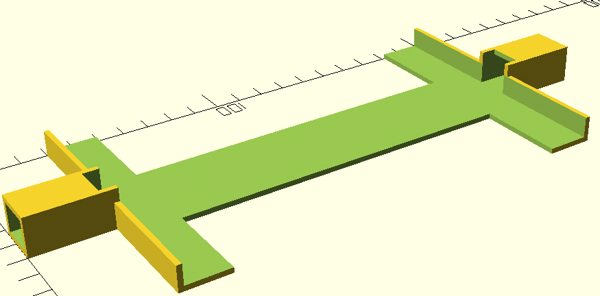 While it isn’t my best work, it’ll get the job down for now.
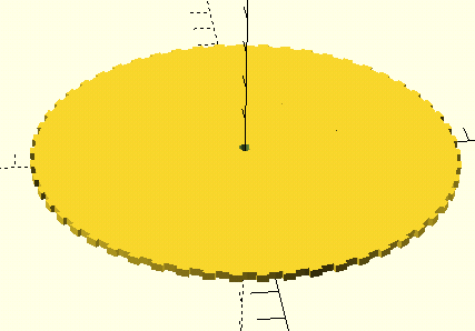
I also needed wheels, and for that I’m just using gears that I made I had to design these custom so they would have the proper amount of grip and would also have the proper D-shaped cutout for my motors:
Now, let’s talk about the code.
PID Control
PID (Proportional, Integral, Derivate) is a very common and relatively simple control scheme used to maintain a set point in a system. In my case, the set point is a pitch angle of 0 degrees, and the control output is the rotation of the motors. If you want to learn more about PID, PID Explained is a very good resource for this. Essentially, you calculate the proportional, integral, and derivative, and the output is the three of those added together. Here is the code for my PID controller:
// The struct representing the controller
typedef struct {
    float kp, ki, kd, target, prev_error, p, i, d, i_sum;
    TickType_t p_time;

} pid_controller_t;
// Functions for using the struct
pid_controller_t pid_controller(float kp, float ki, float kd, float target)
{
    pid_controller_t pid = {
        .kp = kp,
        .ki = ki,
        .kd = kd,
        .target = target,
        .prev_error = 0,
        .p_time = xTaskGetTickCount(),
        .i_sum = 0,
    };
    return pid;
}

float step(pid_controller_t pid, float reading)
{
    float error = 0 - reading;
    TickType_t c_time = xTaskGetTickCount();
    TickType_t delta = (c_time - pid.p_time) * ms_ratio;

    pid.p_time = c_time;
    pid.p = pid.kp * error;

    pid.i_sum += error * delta;
    pid.i = pid.i_sum * pid.ki;

    pid.d = pid.kd * (error - pid.prev_error) * (1 / delta);
    pid.prev_error = error;

    return pid.p + pid.i + pid.d;
}
Essentially, the step function updates the value of i_sum while also computing the motor output. I made a generic PID struct and functions because I will be using a few different PID controllers in this project (One for balancing, one for rotation, one for velocity).
While attempting to tune the PID (Adjusting kp, ki, and kd to balance effectively (This procedure is documented on the PID Explained website)), I realized that there is a minor oversight in my prototype.
A self-balancing robot is attempting to balance what is known as an inverted pendulum. My design for the robot chassis does not have a high center of mass so it can’t balance like an inverted pendulum. In fact, it’s so light the the wires connected to the buck converter and ESP-32 are actually throwing it off balance. I need to redesign the robot so that it has a position for a weight above its center.
A hiatus, and more problems
It’s been a while since I’ve updated this. This project is still in progress, but I’ve had a few problems that I will explain here in case it helps somebody else avoid my fate in the future.
The first problem: Weak motors
This problem was the most expensive one to solve. After looking at my robot more closely, I realized the motors were too weak to effectively control the robot. I reached out to an engineering student friend of mine to ask about this, and after he explained the calculations, I did them and realized my motors were significantly weaker than I thought they were. I won’t go through most of the calculations here (feel free to reach out if you’re curious) but you essentially must calculate the required torque based on the eventual weight of your two-wheel robot. Using this, you need to calculate the driving resistance, and the force required to balance the robot (For this last part, I overestimated theta to be 45 degrees, despite this being incredibly unlikely to recover from). After you find these forces, add them and multiply this by the wheel radius to get your torque.
After I figured out the torque, I needed to buy new motors. These were wildly more expensive than the existing ones I had, as well as a lot bigger. I wired them up and they seemed to sort of work, but they were behaving unpredictably. I then realized I forgot to account for their current needs in my power supply.
The second problem: A weak power supply
Finding a new power supply was a chore, because I was previously using a buck converter and these are limited to 3A maximum current. These draw 2A-3A each so that wouldn’t work. I simply could not find a wired solution that would do what I needed, so I switched to using AA batteries and no converter. This has the benefit of being disconnected from the wall, and if I put the batteries at the top of my robot it helps the inverted pendulum become more stable. I have two packs of 4 AA batteries in parallel, which is a little over 6 volts. This setup supplies a lot more current.
The third problem: A weak motor driver
After setting this up, I decided to check the maximum current of my motor driver just in case it would be unable to drive my motors; it’s a good thing I did. Turns out, the motor driver can only supply 1.2A of continuous current! This is a pitifully small amount that would absolutely not be able to run these new motors. I had to buy a new motor driver, which (following the theme) was significantly more expensive. I am now waiting for this to arrive.
A new chassis
The silver lining to all of these problems is that I was able to redesign my robot chassis. It now uses a design inspired by some existing two-wheeled robots, with flat platforms for the electronics that are supported by metal poles on the sides. This approach is way more flexible, and also just looks way better and was easier to model. I’ll add a picture soon.
Check back soon for more updates!